

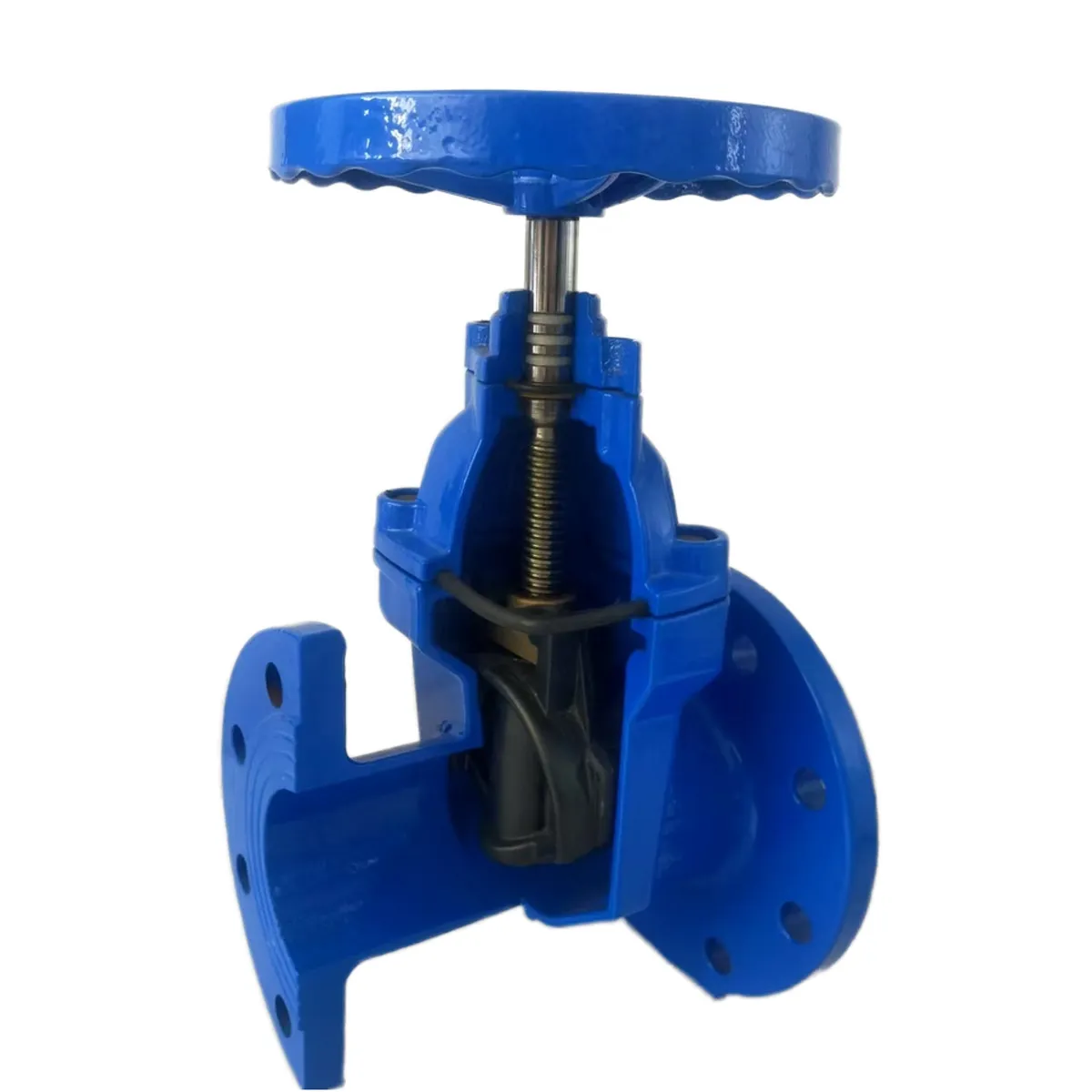
A gate valve is one of the simplest machines in a water network: a wedge that travels between two seats, driven by a multi-turn stem. Yet most gate valve failures trace back not to design but to what happened around it. An unflushed pipeline. A flange forced into alignment. A stem that seized after years of neglect. This guide covers the field practices that most affect gate valve service life: receiving checks, installation, operation, and an exercising program. The material is drawn from public utility procedures and AWWA guidance, with examples from the resilient-seated and metal-seated gate valves we supply.
Before installation: receiving checks and storage
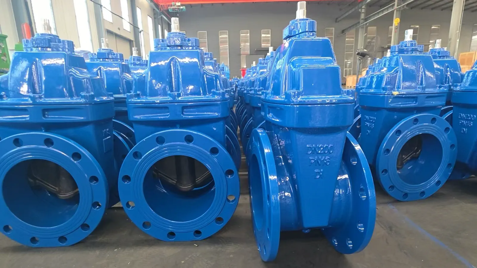
Most installation problems can be caught before the valve reaches the trench. Inspect for transit damage: bent stems, cracked handwheels, loose bonnet bolts, scratched flange faces, and cuts or exposed metal on the rubber seat of resilient-seated valves.
Cycle the valve through one full open-close operation before installation. This confirms free travel and clear open/closed marking. If it binds, report it to the supplier before the pipeline is buried.
Orientation, support and alignment
On a horizontal pipeline, install the valve with the stem vertical and upward. This keeps the bonnet accessible and prevents debris settling around the wedge guides. A rising stem should never point downward: condensate collects on the exposed threads and accelerates corrosion.
The valve must never carry the pipeline's weight. Place pipe supports on both sides so the body, flanges and bonnet take no bending load. If the pipe does not line up, fix the supports; do not pull the line into alignment with the flange bolts. A joint forced into alignment seals for a week but leaves the body and gasket under permanent stress, which shows up later as flange leakage or a distorted seating angle.
Complete all pipeline welding first, let the joint cool to ambient temperature, and only then install the valve. Welding with the valve in the line can push enough heat into the body to damage EPDM seating surfaces permanently.
Flush the pipeline before operating the valve under load. Weld slag, sand, and construction debris are the most common cause of scored seats and jammed wedge guides on a first operation. Where a line feeds pumps or sensitive equipment, a Y-type strainer upstream catches this debris continuously — see our Y-Type Strainers as one example.
Flanged connections: gaskets and bolt tightening
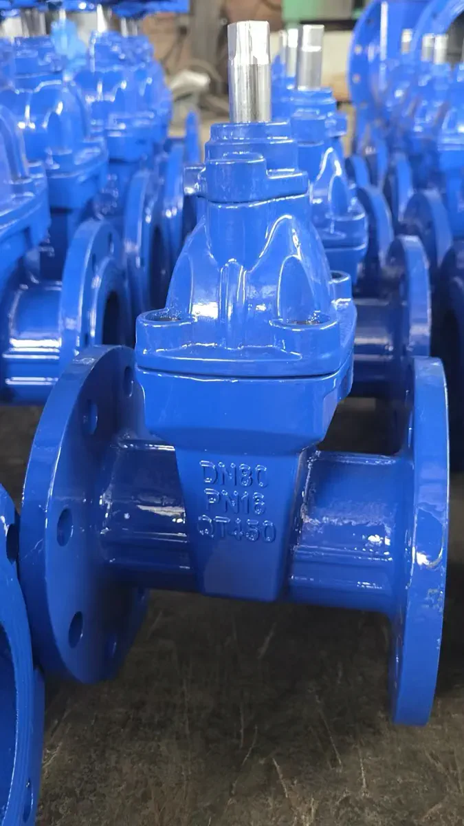
The bolted flange is the most common leak path on an installed gate valve. Clean both flange faces and centre the gasket before inserting bolts, then hand-tighten in a star (cross) pattern. Tighten in stages — commonly 30%, 60% and 100% of target torque — in the same pattern with a calibrated torque wrench, using values matched to the gasket material and flange rating. Re-check after about 24 hours, once gasket relaxation has settled.
Gasket material must match the fluid, temperature and pressure of the line. A mismatch fails no matter how carefully it is torqued. For threaded ends, apply thread sealant or PTFE tape in the direction of the thread, hand-tighten, then snug with a wrench. Over-torquing can crack a ductile-iron or cast-iron body outright.
Protecting buried valves: coatings, polywrap and access
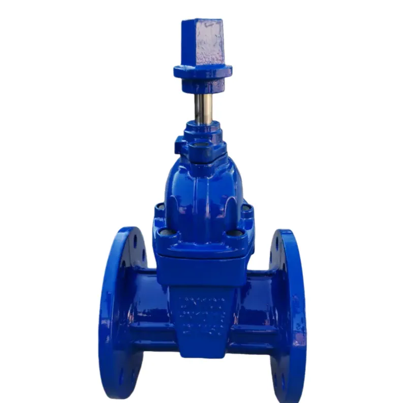
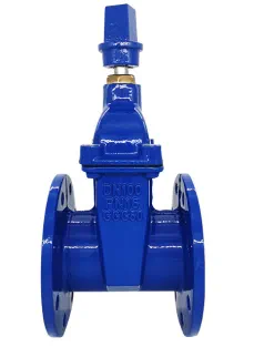
Buried valves live in the most corrosive environment in the network, so corrosion protection is a maintenance topic, not just a purchase specification. Fusion-bonded epoxy is the standard protective coating for valve bodies; AWWA C550 sets the requirements for protective epoxy interior coatings on valves and hydrants. In aggressive soils, polyethylene encasement over the valve and adjacent pipe adds a further barrier, the approach defined for ductile-iron systems in AWWA C105. Our Buried Gate Valve (MZ45X / MZ45T) follows this logic, with full epoxy coating and a polywrap option for direct-burial installation.
Access is the other half of buried-valve maintenance. Position the valve box directly above the operating nut, and use extension spindles or gearboxes in deep trenches so the valve can be operated from ground level. A buried valve that cannot be reached without excavation is, for practical purposes, not maintained at all. Record the as-built location, turns-to-close and closing direction at commissioning.
Operating rules: full open or full closed, never throttling
A gate valve is an isolation valve. It is designed to sit fully open or fully closed, and throttling is the fastest way to destroy its seating surfaces. With the wedge held partially open, high-velocity flow across the seats causes vibration and erosion that quickly turn a bubble-tight valve into a leaking one. Where flow regulation is required, a control valve such as our Pressure Reducing Valve (200X) is the right tool.
Two operating habits extend valve life. First, after driving to the full-open stop, back the handwheel off about one turn (some utilities use a quarter to half a turn). This prevents the wedge from jamming and makes the open state unmistakable. Second, close firmly but stop once the valve is leak-tight. Driving the wedge past the stop deforms the seating surfaces and raises the torque needed for every future closure. On large-diameter valves, equalizing pressure across the wedge before operation, where the system allows it, reduces seat load and operating torque.
Position visibility also reduces operating errors. Non-rising-stem valves give no external clue to the wedge position, which is why designs with a position indicator, such as our Position Indicator Gate Valve, are used where an operator must confirm valve status at a glance. In fire service mains, supervisory-switch valves like our Fire Signal Gate Valve send open/closed feedback to the control panel instead.
Building a valve exercising program
A valve that never moves is a valve that is failing silently. Stem threads corrode, packing takes a compression set, and debris accumulates around the wedge, until the day the valve must isolate a main break.
AWWA Manual M44, *Distribution Valves: Selection, Installation, Field Testing, and Maintenance*, is the reference manual for valve exercising; AWWA Standard G200 covers distribution-system operation and management, including valve programs. M44's self-assessment sets the baseline at exercising each valve at least every three years. Utilities commonly exercise large-diameter valves and those serving critical facilities such as hospitals more often.
A practical exercising sequence, as documented in utility SOPs, runs as follows:
1. Locate and uncover the valve; confirm it matches the system map.
2. Record the direction of opening and the number of turns to fully close.
3. Exercise the valve through two to three full open-close cycles.
4. Return it to its normal position and confirm no leakage at the packing, flanges, and valve box; enter the valve's condition in the asset system.
Valves that cannot complete full travel should be flagged for repair rather than simply noted. A valve that cannot fully close is a liability during emergency isolation, and the exercising record turns that discovery into a scheduled work order.
Routine maintenance checklist
- Gland packing. Slight seepage at the stem is common. Tighten the gland nuts evenly in small increments, and if that does not stop the leak, replace the packing. Do not overtighten; it binds the stem and wears it.
- Exposed stems (OS&Y designs). Clean the exposed thread and apply compatible lubricant. Rising stems sit in weather and corrode fastest. Our OS&Y Resilient Seated Gate Valve and AWWA Resilient Gate Valve (OS&Y) use this rising-stem layout, where the visible stem confirms open/closed position at a glance.
- Gearboxes. Check oil level and condition on gear-operated valves, and confirm the manual override works.
- Coating condition. Touch up damaged epoxy promptly, especially at flange edges and bolt holes, to keep the corrosion barrier intact.
- Internal seats. Increasing closing torque or rising leakage at full close signals debris or wear on the seating faces. Resilient seats are replaced; metal-to-metal seats, such as those on our Metal Seated Gate Valve and, for hotter services, the DIN 3352 F4 Metal-Seated Gate Valve (rated up to about 120 °C), can often be re-lapped at overhaul.
- Water hammer. Repeated pressure surges stress seats and bodies. Slow-closing valves and spring-assisted check valves, such as our Silent Check Valve (HC41X), address the cause at pump discharge.
- Buried valves. Where a valve resists operation after long inactivity, use a valve exerciser with controlled torque rather than forcing the handwheel. If travel cannot be restored, schedule replacement.
Choosing the right valve body for the duty
Maintenance expectations differ by valve family, so it pays to match the valve to the service at specification stage rather than after failure. The table below summarises the main gate valve types we supply:
For German or American specifications, our DIN 3352 F4 Resilient Gate Valve (NRS), DIN 3352 F5 Resilient Gate Valve (NRS), and AWWA Resilient Gate Valve (NRS) — the AWWA series in a 200 psi class with UL / FM listing options — follow the corresponding national standards (AWWA C509 / C515), so spare wedges, stems and packing can be maintained against a defined reference. Size ranges and pressure classes as listed on our product pages are the figures currently published; final confirmation of ratings for a specific order should be made with the factory.
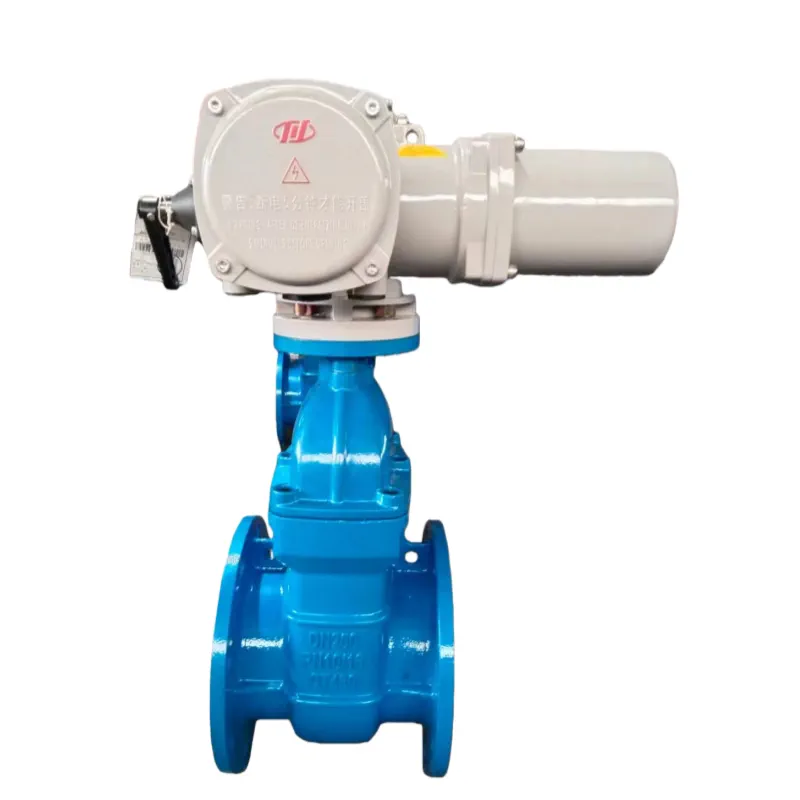
Actuated valves extend the exercising program into remote cycling. Our Electric Gate Valve (Z945X / Z941X) supports SCADA-based operation without dispatching crews.
| Product | Size range | Pressure class | Seat / sealing | Body / coating | Standards |
|---|---|---|---|---|---|
| Resilient Seated Gate Valve (NRS) | DN40 – DN600 | PN10 / PN16 | EPDM resilient | Ductile iron QT450 (GGG40), fusion-bonded epoxy | BS 5163-1:2004 / BS EN 1074-2:2000 |
| OS&Y Resilient Seated Gate Valve | DN40 – DN600 | PN10 / PN16 | EPDM resilient | Ductile iron QT450, epoxy | GB / BS 5163-1:2004 / DIN 3352 F4 / AWWA |
| Metal Seated Gate Valve | DN50 – DN600 | PN10 / PN16 / PN25 | Metal-to-metal | Ductile iron / carbon steel, epoxy | GB / BS 5163-1:2004 / DIN 3352 F4 |
| DIN 3352 F4 Metal-Seated Gate Valve (NRS) | DN50 – DN300 | — | Metal (bronze ring) | Cast iron / ductile iron | GB / BS 5163-1:2004 / DIN 3352 F4 |
| Buried Gate Valve (MZ45X / MZ45T) | DN50 – DN600 | — | EPDM (X) / metal (T) | Epoxy-coated, polywrap option | Direct burial design |
Sources
- AWWA Manual M44 — *Distribution Valves: Selection, Installation, Field Testing, and Maintenance*, American Water Works Association.
- AWWA Standard G200 — *Distribution Systems Operation and Management*, American Water Works Association.
- City of Flint, SOP #331 — *Valve Inspection, Exercising, and Maintenance*, Rev 0.0, January 2018 (torque limits, fault handling and exercising procedure; frequencies deferred to AWWA M44).
- AWWA C550 — *Protective (Epoxy) Interior Coatings for Valves and Hydrants*.
- AWWA C105/A21.5 — *Polyethylene Encasement for Ductile-Iron Pipe Systems*.
- BS 5163-1:2004 — *Valves for waterworks purposes. Predominantly key-operated cast iron gate valves — code of practice* (supersedes BS 5163:1986), British Standards Institution.
- BS EN 1074-2:2000 — *Valves for water supply. Fitness for purpose requirements and appropriate verification tests. Part 2: Isolating valves*.
- Product specifications as published on our product pages (sizes, materials, pressure classes, seating, and standards for the valves referenced above).
Frequently Asked Questions
Related Products
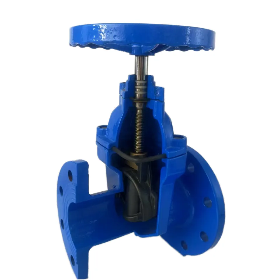
Resilient Seated Gate Valve (NRS)
S4 / S5 · DN40 – DN600 · BS5163 / EN 1074-2
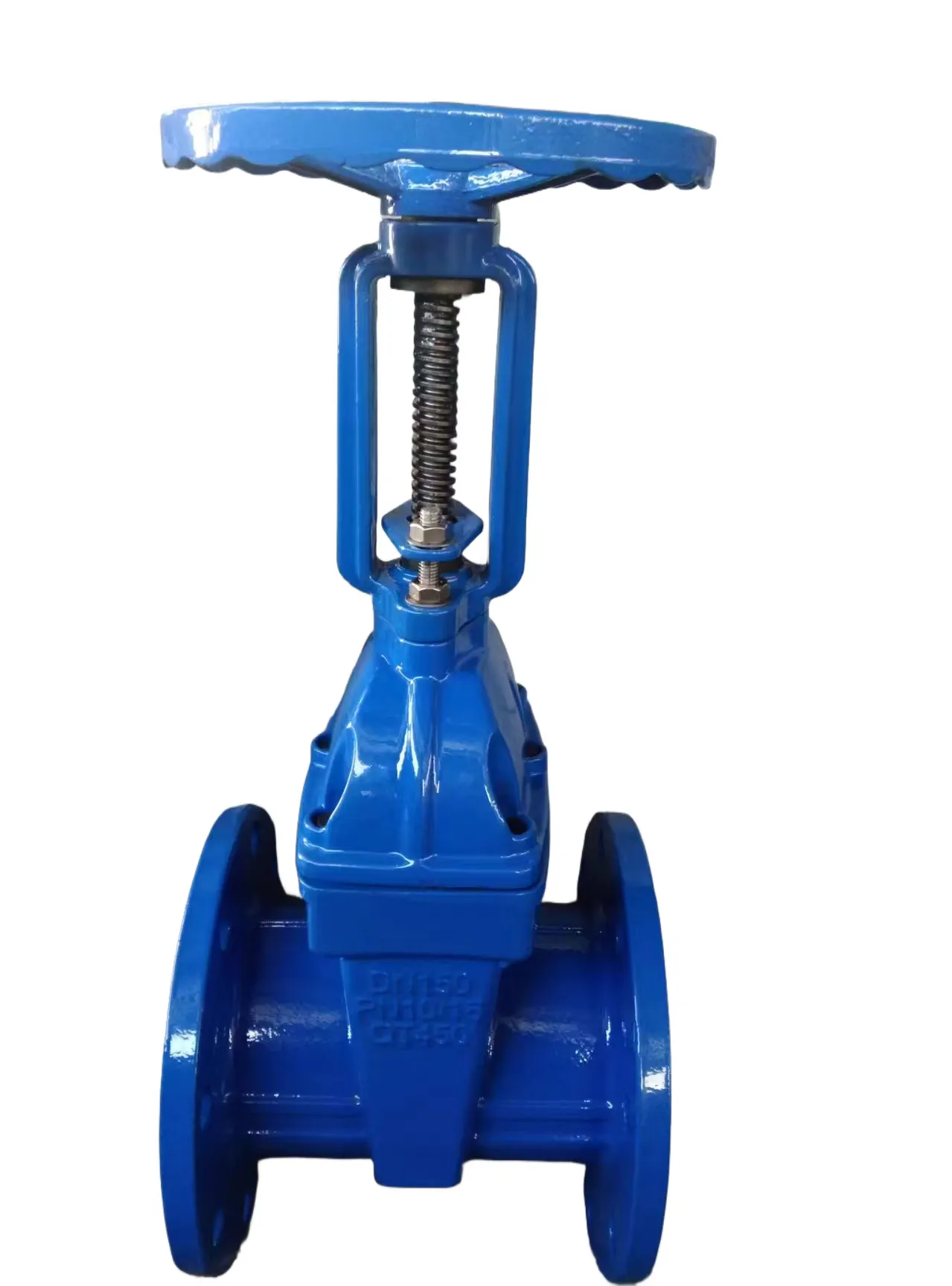
OS&Y Resilient Seated Gate Valve
OS&Y · DN40 – DN600 · GB / BS5163 / DIN F4 / AWWA
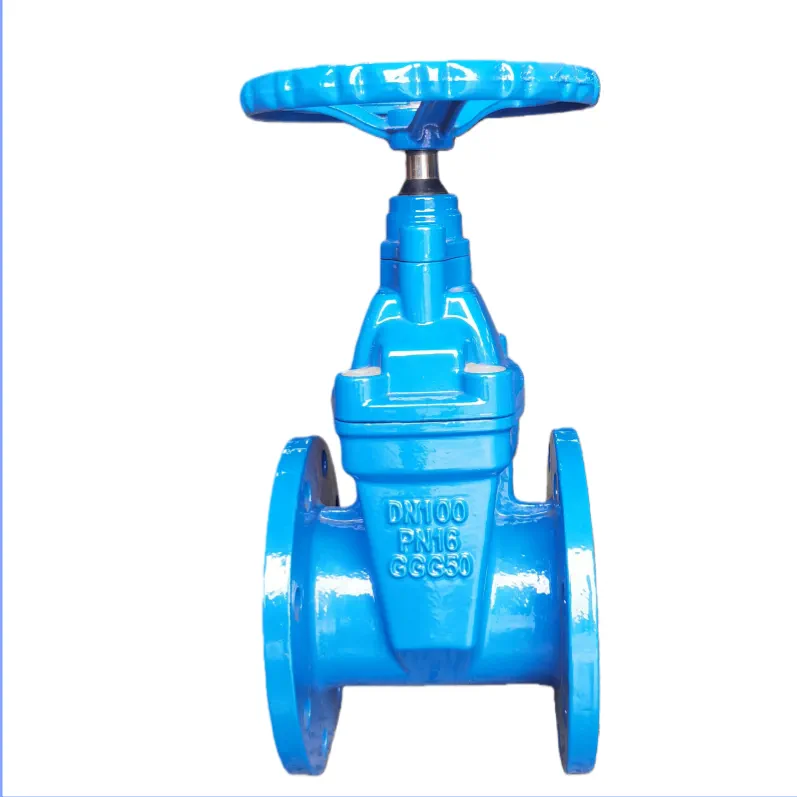
DIN F4 Resilient Gate Valve (NRS)
DIN 3352 F4 · DN50 – DN600 · PN10/16
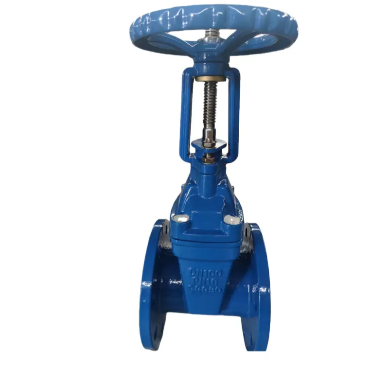
DIN F4 Resilient Gate Valve (OS&Y)
DIN 3352 F4 · DN50 – DN600 · PN10/16
Buried Gate Valve (MZ45X / MZ45T)
MZ45X / MZ45T · DN50 – DN600
Electric Gate Valve (Z945X / Z941X)
Z945X / Z945T / Z941X / Z941T