
When a pump trips or a valve closes too fast, the water column behind it does not decelerate smoothly. It stops almost instantly, and the pressure spike that follows is one of the most destructive forces in a piped water system. This guide covers where water hammer comes from, why pumping stations concentrate the risk, and which valve functions (check, slow-close, relief and air) hold the pressure wave in check.
What water hammer is and why the numbers matter
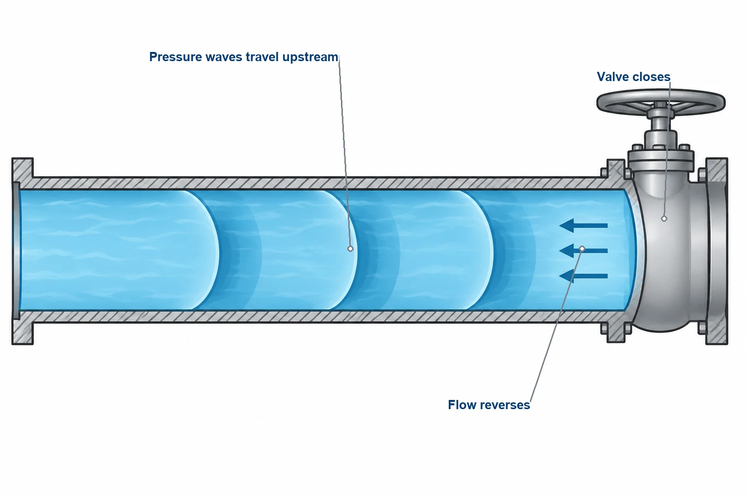
Water hammer, formally a hydraulic transient or surge, is the pressure wave generated whenever the velocity of a water column changes abruptly. The governing relationship is the Joukowsky equation, first published in 1898 and still the basis of every first-pass surge estimate: pressure rise equals fluid density × wave speed × velocity change. In units, Δp = ρ · a · Δv, so 1,000 kg/m³ × 1,200 m/s × 0.3 m/s = 360,000 Pa. That is the arithmetic behind the figures below.
The numbers grow quickly. At a wave speed of roughly 1,200 m/s, typical of water in rigid metallic mains such as ductile iron, a sudden velocity change of just 0.3 m/s (about 1 ft/s) produces a theoretical surge of around 360 kPa (approximately 50 psi). That spike sits on top of the normal operating pressure, and it comes from a velocity change most operators would call trivial. Run the same arithmetic on a pump at 2 m/s stopped effectively instantaneously and the theoretical maximum is roughly 2,400 kPa (about 350 psi).
Two qualifications keep this honest. Real events rarely reach the theoretical maximum, because closure is never instantaneous and the pipe and its supports absorb some energy. And the equation is a screening tool, not a design calculation. Full surge-analysis methodology should precede equipment selection; AWWA Manual M11 carries it.
Why pumping stations concentrate the risk
A pumping station packs several transient sources into one small footprint.
Pump trips are the most common. A power failure stops the impeller almost immediately while the water column downstream keeps moving. Flow reverses through the pump, and the column can separate and rejoin.
Check valve duty follows from that. The discharge check valve has to close before significant reverse flow develops. If it waits for the reversal, the disc slams onto its seat at full reverse velocity.
Filling and draining operations add a third source. Air behaves unpredictably during filling, and an unvented high point can amplify a surge rather than absorb it.
Long transmission mains scale the problem with pipe length. The characteristic period of a pipeline is the time a pressure wave takes to travel to the nearest reflection point (a reservoir, tank or major junction) and back. A valve or pump event faster than that period develops close to the full theoretical surge.
Each source has a valve-based countermeasure, which is why a well-specified pump station reads like a coordinated valve ensemble.
Check valves: closing before the flow reverses
The check valve is the first defense at a pump discharge, and how it closes usually decides whether surge control works.
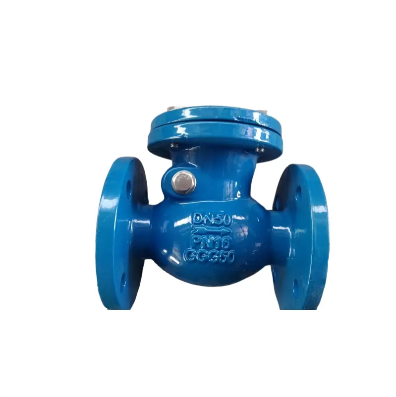
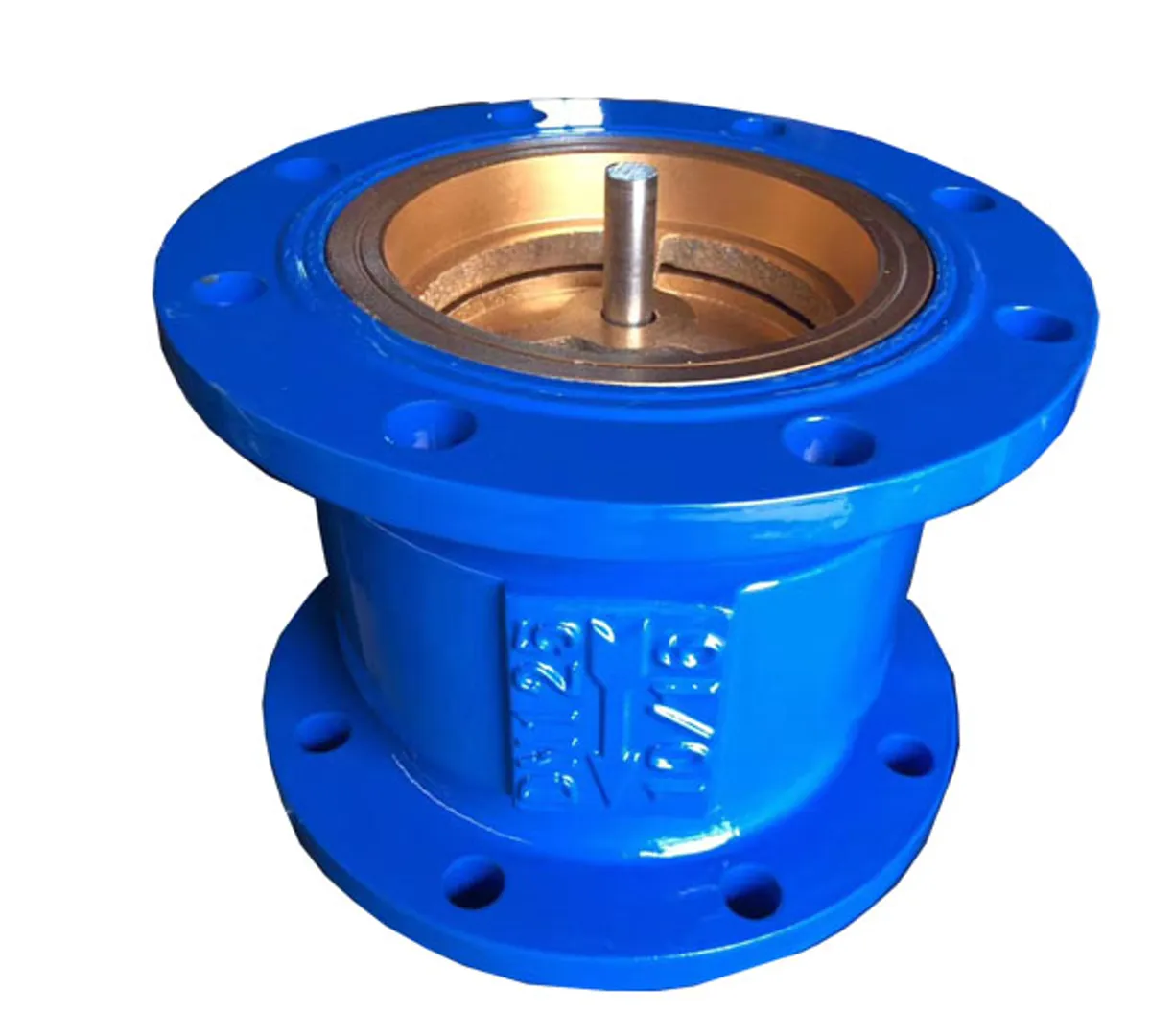
A conventional swing-type check closes because reverse flow pushes the disc onto its seat. That is simple and low-loss, but it means the valve acts only after the water column has already reversed, and the resulting slam is itself a transient event. The listed Swing Check Valve (DIN F6) is a full-bore swing design for high-flow pipelines where pressure loss matters most, with brass-welded or EPDM seating, a 304 stainless-steel guide shaft and an epoxy-coated ductile iron body, in sizes DN50–DN400 for water and wastewater service.
Where water hammer control is a priority, two other patterns are used.
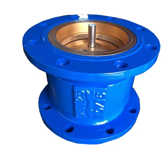
Spring-assisted silent checks hold a spring-loaded disc that begins closing while flow is still moving forward, so the disc meets the seat before reverse velocity can build. The listed Silent Check Valve (HC41X) is a spring-assisted closing valve with an EPDM seal, a 304 stainless-steel spring and an epoxy-coated ductile iron body, listed in DN50–DN400 for water and HVAC service.
Pilot-operated slow-close checks take the opposite approach on larger mains: the closing stroke is deliberately damped over a controlled period, decelerating the water column gently instead of stopping it abruptly. The listed Slow-Shutoff Check Valve (300X) is a pilot-operated slow-close check valve with an epoxy-coated ductile iron body, listed in DN50–DN400 for water and HVAC service.
The choice is hydraulic. Smaller risers commonly take the spring-assisted pattern, while long pump discharge mains, where the water column is heavy, are the classic territory of the slow-close design. Exact selection, closing settings and pressure classes for a specific order should be confirmed with the factory.
Air valves: the piece most often missed
The least intuitive part of surge control is air. When pressure in a falling water column drops to vapor pressure, the column separates and leaves a vapor cavity. When the columns rejoin, they collide. That rejoining event can produce a pressure peak larger than the initiating surge, and it is one reason transient references such as AWWA Manual M51 treat air valves as surge protection rather than simple vents. The phenomenon is column separation, and it happens most often at high points and on long descending profiles.
Air admitted deliberately at those locations cushions the cavity: an air valve that opens under vacuum lets air in quickly, limits the sub-atmospheric pressure, and slows the rejoining of the columns. AWWA Manual M51 treats the role of air valves during unsteady flow as a core chapter topic, and the valve types themselves are covered by ANSI/AWWA C512, whose current edition was published in 2025.
Three air valve functions matter at the risky locations.
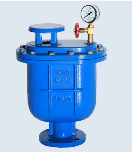
Continuous venting plus vacuum admission is one. The listed Combination Air Valve (CARX) combines bulk air release with continuous venting in DN50–DN200, in a flanged epoxy-coated ductile iron body listed for water transmission service.
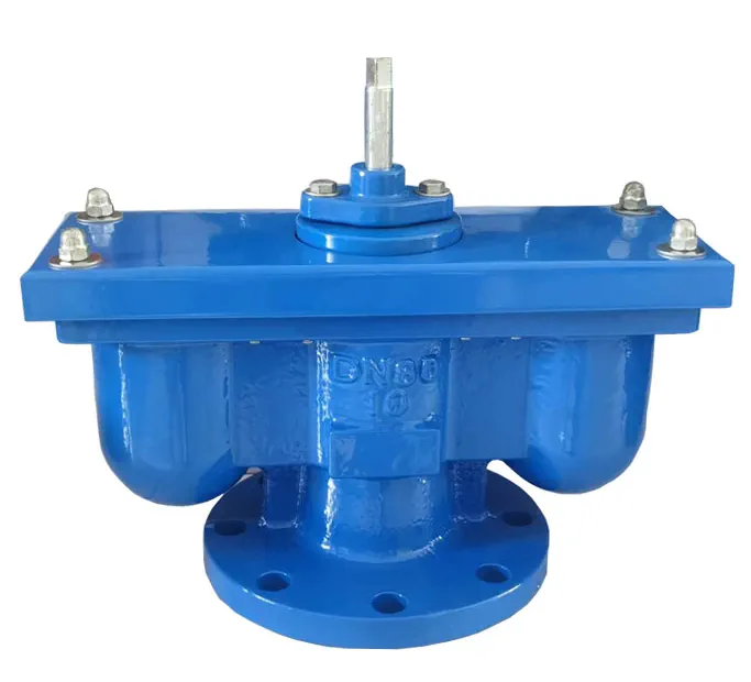
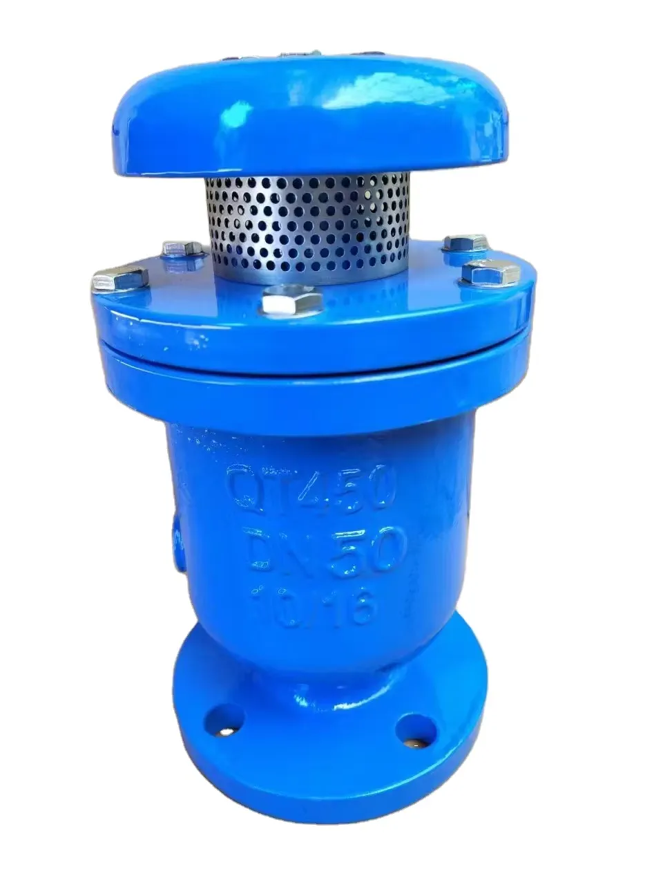
Large and small orifices in one body is another. The listed Double Orifice Air Valve (QB2) pairs a large and a small orifice in one flanged epoxy-coated ductile iron body, in DN50–DN200, listed for water and industrial service.
High-speed discharge during filling is the third. The listed High Speed Exhaust Air Valve (FGP4X) handles high-speed bulk air discharge in DN50–DN150, in a flanged epoxy-coated ductile iron body listed for water mains service.
An air valve that has seized shut protects nothing. These are the valves whose maintenance interval decides whether the surge design on paper still exists in the field.
Relief and pressure control as the backstop
Even with good check valve and air valve practice, residual transients ride on top of the operating pressure. A relief function gives the pressure wave somewhere to go: the valve opens above a set point, spills the excess, and reseats when the event passes.
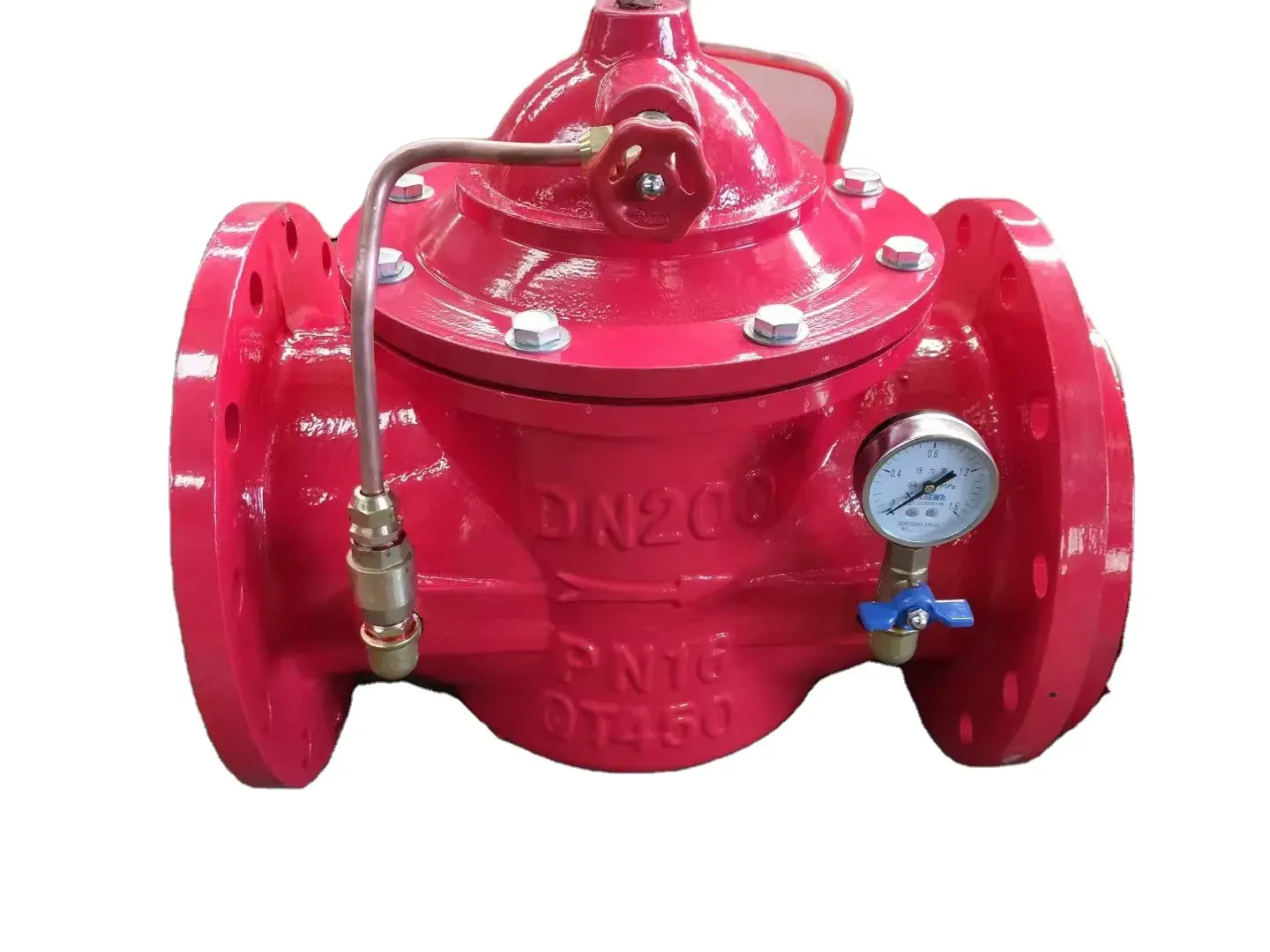
The listed Pressure Sustaining / Relief Valve (500X) is a pilot-operated valve in DN50–DN400 whose listed function is pressure sustaining and relief, with a stainless-steel pilot and an epoxy-coated ductile iron body, listed for water service. In the station layout it is the last mechanical backstop behind the check and air valve functions.
For isolation duty inside the station, operating speed is itself a control variable. A worm-gear operator reduces how quickly a valve can be turned compared with a lever handle, a small mechanical detail that matters on lines where fast closure is a surge risk. The listed Flanged Butterfly Valve with Worm Gear (D341X) is a flanged, gear-operated isolation valve in DN100 for PN10/PN16 service, with an SS304 disc and EPDM seat.
A valve map for a typical pump station
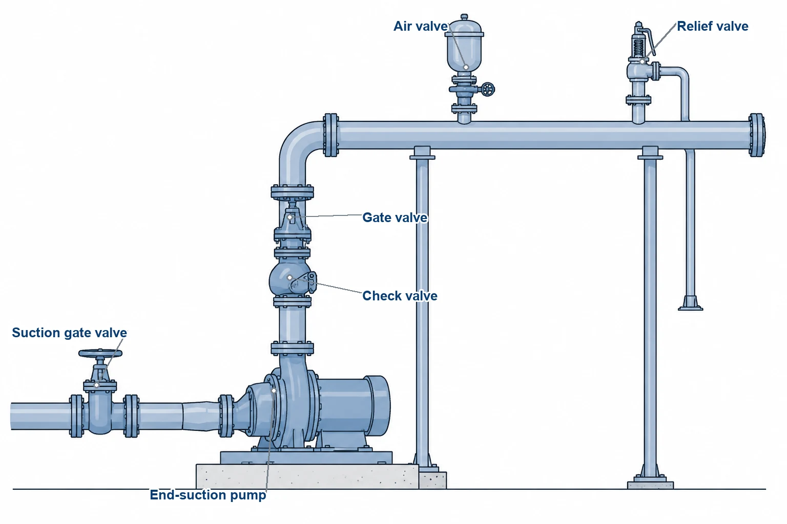
The map is a starting point for specification discussions, not a substitute for a transient analysis of the actual system: pipe material, profile, length and pump inertia all move the answer.
| Surge risk | Typical location | Valve function that addresses it | Listed pattern |
|---|---|---|---|
| Check slam on pump stop | Pump discharge | Spring-assisted closing before flow reversal | Silent Check Valve (HC41X), DN50–DN400 |
| Heavy water column on long mains | Pump discharge, transmission | Pilot-operated slow-close action | Slow-Shutoff Check Valve (300X), DN50–DN400 |
| Residual over-pressure from transients | Pump discharge, pressure zones | Pressure sustaining and relief | Pressure Sustaining / Relief Valve (500X), DN50–DN400 |
| Column separation at high points | High points along the main | Vacuum air admission plus continuous venting | Combination Air Valve (CARX), DN50–DN200 |
| Air management during filling | Filling points, transmission mains | High-speed bulk air discharge | High Speed Exhaust Air Valve (FGP4X), DN50–DN150 |
| Low-pressure-loss duty where surge is managed elsewhere | High-flow pipelines | Full-bore swing check | Swing Check Valve (DIN F6), DN50–DN400 |
| Uncontrolled manual closure speed | Isolation duty | Worm-gear travel control | Flanged Butterfly Valve (D341X), DN100 |
Operation and maintenance practices that keep the protection working
- Start and stop pumps in sequence. Ramped start-up and staged stopping keep velocity changes gradual. Where variable-speed drives are fitted, the ramp settings are part of the surge design.
- Do not rely on the isolation valve as a surge device. A manually operated gate or butterfly valve closes in operator-seconds, which is usually slow enough. Automated isolating valves on long mains need their closing times checked against the pipeline's reflection period.
- Inspect air valves on a schedule. A flooded or seized air valve is invisible from the control room. It announces itself only during the transient it was meant to soften.
- Verify relief settings after any system change. A pump impeller change or a new duty point shifts the pressure profile, and the relief set point may need to follow.
- Record and test the closing behavior of check valves. A change in closing sound at a pump stop is often the first audible sign that a disc or spring no longer travels the way it should.
Reference sources
- Joukowsky equation for pressure rise under abrupt velocity change, first published by Nikolai Joukowsky in 1898; the worked figures in this article are derived directly from Δp = ρ · a · Δv using the stated assumed wave speed.
- AWWA Manual M51, *Air Valves: Air Release, Air/Vacuum, and Combination*, Second Edition (2016), reaffirmed as current by AWWA in November 2025 — including its treatment of water hammer effects of air valves. https://store.awwa.org/product/2335
- ANSI/AWWA C512-25, *Air-Release, Air/Vacuum, and Combination Air Valves for Water and Wastewater Service – Metallic Body and Cover* (published October 2025; supersedes C512-2015). https://store.awwa.org/AWWA-C512-25-Air-Release-Air-Vacuum-and-Combination-Air-Valves-for-Water-and-Wastewater-Service-Meta
- AWWA Manual M11, *Steel Pipe: A Guide for Design and Installation*, Fifth Edition (2017) — surge analysis methodology for steel water pipe.
- Listed valve specifications, as published on our product pages.