Entrained and dissolved air is a primary cause of capacity loss, hydraulic surge damage, and vacuum collapse in municipal water mains. Dissolved air separates at pipeline high points, forming pockets that constrict the cross-sectional flow area and amplify pressure transients. When a line drains or pumps trip, those same peaks experience sub-atmospheric pressure that can compromise thin-walled or large-diameter pipe. Properly specified air valves address both operating conditions: venting air during filling, admitting air under vacuum, and continuously expelling micro-bubbles during steady operation. This guide reviews the core operational duties, compares single-orifice, high-speed, and combination designs, outlines sizing calculations, and provides a pre-order supplier verification checklist.
Why Trapped Air and Vacuum Threaten Transmission Pipelines
Raw and treated water conveys considerable air into closed piping. A DN600 transmission line filled at a velocity of 1.0 m/s introduces roughly 280 litres of entrained air per minute. While a portion discharges through terminal outlets, remaining air migrates to intermediate summits along the pipeline profile. Under an operating pressure of 6 bar, compressed air pockets shrink to one-sixth of their atmospheric volume. These high-pressure pockets function as pneumatic springs, creating severe hydraulic instability.
The resulting damage affects mechanical components and overall delivery capacity. Air accumulation throttles the effective internal diameter, driving up local velocities and increasing head loss. In severe cases, pipeline throughput drops to 70% of design capacity. Because air is highly compressible while water is practically incompressible, downstream valve closures cause pressure waves to rebound against these gas pockets. The subsequent rapid compression and expansion generate surge spikes well beyond standard water hammer calculations, leading to joint fatigue and pipe bursts at high points.
Sub-atmospheric pressure presents an equally critical failure mode during pump trips, emergency shutdowns, or rapid line drainage. As the water column separates, internal pressure drops below atmospheric levels. Buried large-diameter steel, HDPE, and PVC lines are vulnerable to buckling from external earth and hydrostatic loads. A buried DN800 line under wet backfill can deform, while thin-walled plastic pipe risks immediate collapse. Sizing the intake orifice correctly ensures adequate atmospheric air ingress, equalising the pressure differential before pipe wall deformation occurs.
The Three Operating Duties: Air Release, Air Ingress, and Bulk Venting
Specifying a generic "air valve" often leads to mismatched hardware. Pipeline engineering recognizes three distinct venting duties, each governed by different orifice dynamics and differential pressures.
The first duty is continuous air release under operating pressure. Water carries between 8 and 20 ppm of dissolved air under typical distribution conditions. As line pressure drops along the hydraulic grade, dissolved gas releases as micro-bubbles and gathers at local summits. A small-orifice mechanism with a buoyant float discharges these accumulations automatically without allowing water to escape.
The second duty is high-capacity air intake for vacuum prevention. When pumps trip or lines drain, the valve seat must open instantly, admitting large volumes of atmospheric air to displace receding water columns. This requires a large-orifice design engineered to stay open under reverse flow differentials without premature shutoff.
The third duty is bulk air discharge during initial pipeline filling. As water charges an empty main, large air volumes ahead of the advancing column must exit rapidly. The valve must vent this air at low backpressure while resisting early aerodynamic closure before the water column reaches the float. Transmission mains typically require combination units that combine large-orifice filling/vacuum capabilities with small-orifice pressurized venting.
QB2, FGP4X, and CARX: Technical Comparison of Core Designs
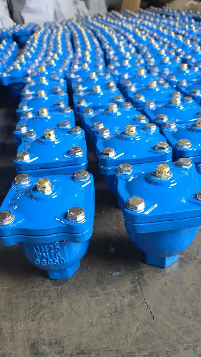
Municipal and industrial water tenders in the Gulf region routinely specify three proven air valve configurations, represented by our standard manufacturing lines.
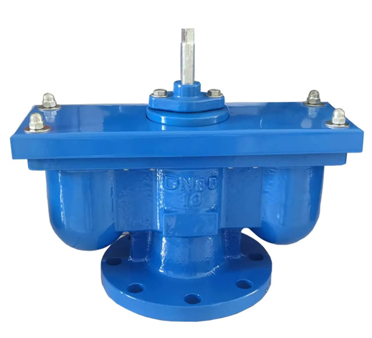
The double-orifice configuration, exemplified by the QB2, integrates independent large and small orifices within a single flanged body. The large orifice governs line filling and vacuum relief, while the small orifice provides continuous micro-venting under operating pressure. Manufactured from ductile iron in nominal sizes DN50 to DN200 with fusion-bonded epoxy coating, it serves as the standard utility valve for municipal distribution, irrigation networks, and industrial utility mains.
The high-speed dynamic design, represented by the FGP4X, is engineered specifically for bulk air transfer along critical transmission lines. Its aerodynamic internal profile prevents premature float closure during high-velocity air discharge, while enabling rapid air intake upon column separation. Typical installations include pump discharge headers and long transmission mains in sizes DN50 to DN150.
The compact combination design, exemplified by the CARX, combines full vacuum protection, rapid exhaust, and continuous pressurized air bleeding inside an integrated float chamber. It is selected for reservoir inlet lines, pump vaults, and distribution networks where chamber dimensions or installation budgets favour a single compact valve body in sizes DN50 to DN200.
The engineering parameters below outline the operational differences across these three configurations.
| Design Parameter | Double Orifice (QB2) | High Speed (FGP4X) | Combination (CARX) |
|---|---|---|---|
| Nominal size range | DN50 – DN200 | DN50 – DN150 | DN50 – DN200 |
| Bulk discharge during filling | Large orifice (standard) | Large orifice, low flow resistance | Large orifice (integrated) |
| Air intake under vacuum | Large orifice (standard) | High-rate intake profile | Large orifice (integrated) |
| Continuous pressurized venting | Integrated small orifice | Not designed for continuous venting | Integrated small orifice |
| Primary mounting locations | Profile peaks, network summits | Pump discharge headers, mains | Reservoir connections, urban vaults |
| Primary service media | Potable water, irrigation, plant piping | Raw and potable transmission mains | Distribution and transmission mains |
Float Mechanics, Sealing Orifices, and Internal Trim Engineering
Air valve operation relies strictly on fluid buoyancy and differential pressure, operating without external actuators, electric supply, or instrumentation. Inside the casing, a precision-machined float moves vertically relative to the liquid level. When trapped air accumulates in the chamber, the liquid level drops, lowering the float and unseating the orifice seal to vent the gas. As liquid refills the chamber, the buoyant float rises to seal against the resilient seat.
Large and small orifices serve distinct aerodynamic and hydrodynamic roles. The large orifice features a wide discharge passage paired with a contoured seat, allowing massive air volumes to escape during filling while cushioning closure as the liquid interface arrives. The small orifice features a precision-drilled nozzle designed to open against full pipeline working pressure, releasing minute gas pockets continuously without weeping.
Internal component metallurgy determines field reliability. Floats must be fabricated from AISI 304 or AISI 316 stainless steel; synthetic floats soften and distort under elevated ambient temperatures, while elastomer-coated hollow floats risk delamination. Sealing seats require vulcanised EPDM compound to ensure resilience across chlorinated water exposure, temperature fluctuations, and cyclic float impact. Valve bodies are cast from ductile iron (EN-GJS-450-10 or ASTM A536) coated with electrostatic fusion-bonded epoxy. Threaded air valves for small-bore utility lines (DN15 to DN50) are available in forged brass or ductile iron.
Hydraulic Placement Rules for Water Transmission Pipelines
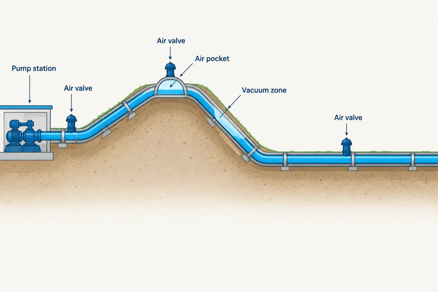
Air valve placement requires systematic hydraulic analysis rather than arbitrary spacing. Pipeline engineers should position valves at every elevation peak along the hydraulic profile, including gentle rises where air can coalesce; immediately downstream of booster pumps and check valves to counter column separation and initial air discharge; at uniform intervals of 400 to 800 metres along extended horizontal gradients; at slope transition breaks where downward flow velocity exceeds horizontal velocity; and directly upstream of bulk flow meters, control valves, and filtration batteries to preserve metering accuracy.
Subsurface installation requires dedicated, well-drained valve chambers. Enclosing an air valve in an unvented, sealed vault creates severe hazards: discharging air can overpressurise the chamber, and standing groundwater can be drawn back through the inlet orifice during vacuum events. Chambers must include a screened exhaust riser terminating above maximum flood level, adequate sump drainage to prevent valve submergence, and isolation gate valves to permit routine servicing without shutting down the transmission main.
Sizing Methodology: Orifice Sizing Based on Flow, Not Line Diameter
Matching the air valve nominal size directly to the pipeline diameter is an engineering error. A DN600 pipeline rarely requires a DN600 air valve; it typically specifies a DN80 to DN150 valve body selected through two independent flow calculations.
Large-orifice exhaust sizing depends on the maximum planned pipeline filling rate. The volume of expelled air equals the water displacement rate plus the entrained air the water carries. Based on standard design fill velocities of 0.3 to 1.0 m/s, the discharge orifice area is determined from manufacturer performance charts to ensure differential air pressure inside the pipe does not exceed 0.5 bar during filling. Undersized exhaust ports create backpressure, risk line vapour-lock, and impede pump priming.
Vacuum sizing calculates the intake capacity required during emergency drainage or pump trip column separation. The intake orifice must draw atmospheric air at a volumetric rate matching the maximum possible liquid outflow, maintaining internal line vacuum within 0.2 bar below atmospheric pressure. Deep gravity discharge profiles and thin-walled pipes require thorough intake verification.
Small-orifice venting capacity is determined by operating pressure and dissolved air release rates, typically calculated from water temperature and system pressure drops. Standardized small-orifice diameters (typically 1.5 to 3.0 mm) provide sufficient release capacity at 6 to 10 bar working pressures. Sizing comparisons should evaluate certified cubic-metre venting curves rather than nominal flange dimensions.
Valve pressure classes must align with overall pipeline ratings: PN10 for gravity networks, PN16 for conventional pumped distribution, and PN25 or higher for high-head transmission mains. All units require factory pressure testing to 1.5 times nominal rating for the shell and 1.1 times for the seat, verified across both seated and buoyant float states.
Manufacturing Standards and Regulatory Compliance: EN 1074-4, AWWA C512, and SABER
Waterworks tenders across the Middle East and international markets reference two established product standards. EN 1074-4 defines European requirements for air valve design, casing integrity, venting capacity, and flow resistance. AWWA C512 specifies North American standards for air release, air/vacuum, and combination valves in waterworks systems, frequently specified across Saudi and Gulf EPC projects with US engineering lineage.
These standards employ differing flow measurement protocols and reporting criteria. Capacity figures certified under AWWA C512 cannot be evaluated interchangeably with EN 1074-4 test data without adjusting for test pressure differentials. Procurement specifications should clearly cite the governing standard and mandate certified aerodynamic test curves.
For infrastructure tenders in the Kingdom of Saudi Arabia, imported waterworks valves fall under SASO technical regulations and must clear the SABER platform. Importers must secure both the Product Certificate of Conformity (PCoC) and Shipment Certificate of Conformity (SCoC). Factoring conformity assessment lead times into project procurement schedules avoids port clearance delays.
Procurement Inspection Checklist: Supplier Verification Parameters
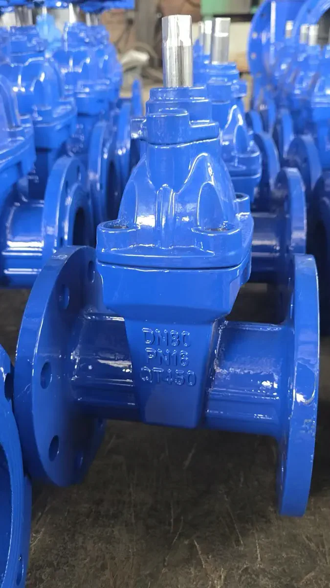
Air valves represent a small fraction of pipeline capital expenditure but can trigger severe line damage if manufactured to substandard tolerances. Before approving supplier submittals, verify the following core parameters.
First, demand certified capacity curves detailing air discharge and air intake volumes across defined pressure drops, rather than accepting unverified catalog tables. Second, confirm float metallurgy is grade 304 or 316 stainless steel with documented material test reports (MTR). Third, ensure the resilient seat compound is virgin EPDM certified for drinking water duty and resistant to chloramine degradation. Fourth, mandate ductile iron bodies with fusion-bonded epoxy (minimum 250 microns dry film thickness) compliant with DIN 30677-2 or GSK quality standards.
Fifth, inspect batch hydrostatic test records confirming 1.5× shell pressure and low-pressure seat sealing (minimum 0.5 bar seat bubble test). Sixth, verify vacuum performance ratings to confirm the float does not lock closed under incoming airflow. Seventh, confirm availability of wear component kits (floats, seals, and seat rings) to support scheduled operational maintenance over project design life.
Frequently Asked Questions
Related Products
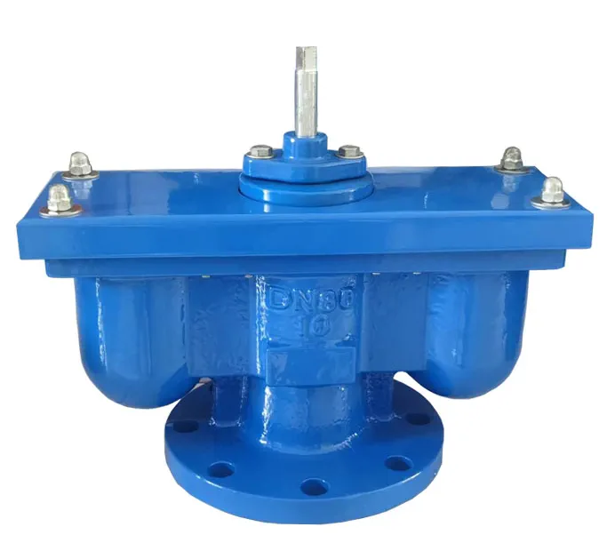
Double Orifice Air Valve (QB2)
QB2 · DN50 – DN200
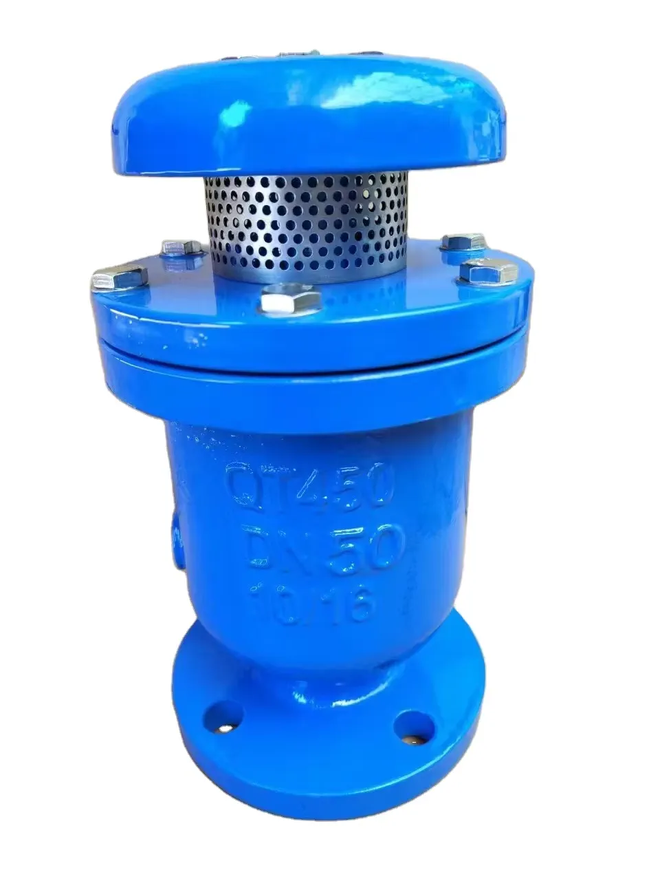
High Speed Exhaust Air Valve (FGP4X)
FGP4X · DN50 – DN150

Combination Air Valve (CARX)
CARX · DN50 – DN200
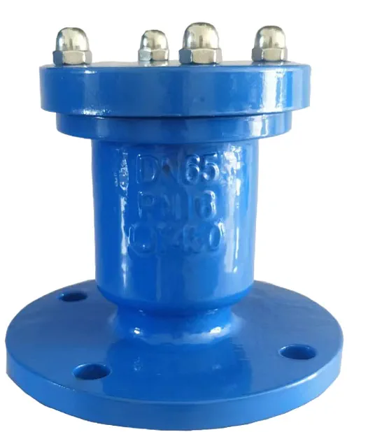
Single Orifice Air Valve
Single Orifice · DN15 – DN50
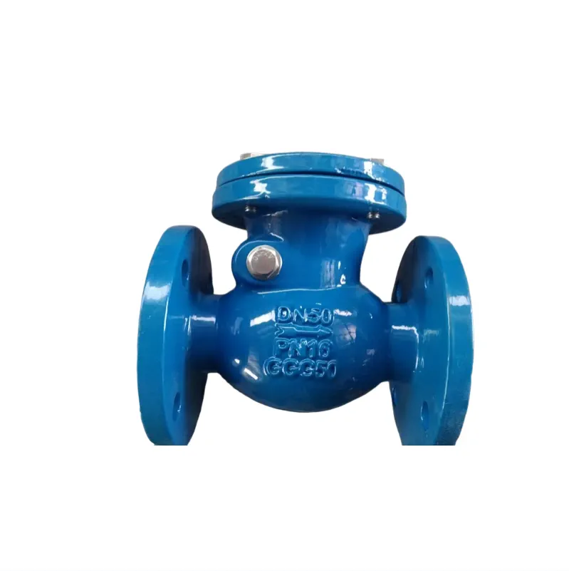
Swing Check Valve (DIN F6)
DIN F6-H44T · DN50 – DN400
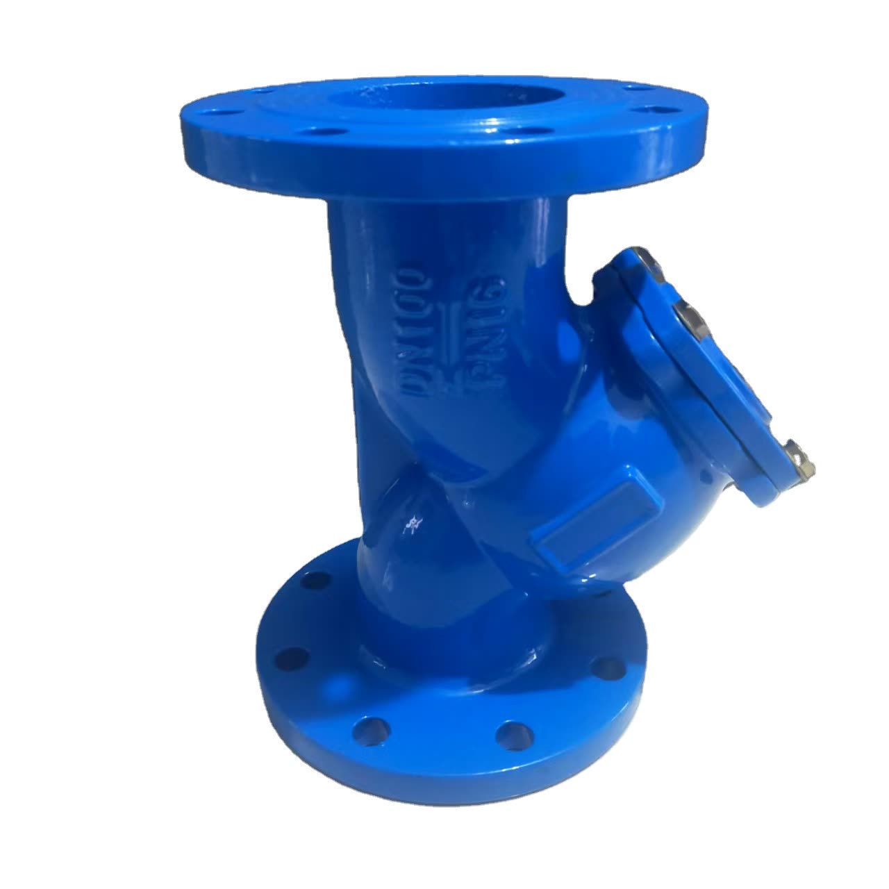
Y-Type Strainers
GL41H / DIN F1 · DN15 – DN400