
When buyers compare butterfly valve quotations, they usually compare pressure class, body material and price, and leave the end connection as a detail to settle later. It is not a detail. The connection decides how heavy the valve is, how long it is, how many bolts and gaskets each joint needs, how carefully it must be installed, and, the part that surprises people, whether the valve can ever be removed for service without cutting or spreading the pipeline around it. This guide covers how wafer and flanged butterfly valves mount, what the face-to-face standards say, where each connection fits, and the questions that settle the choice on a project.
How wafer and flanged butterfly valves mount
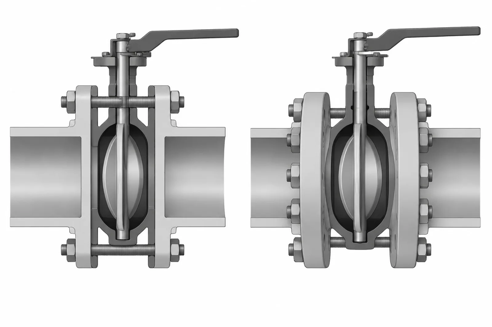
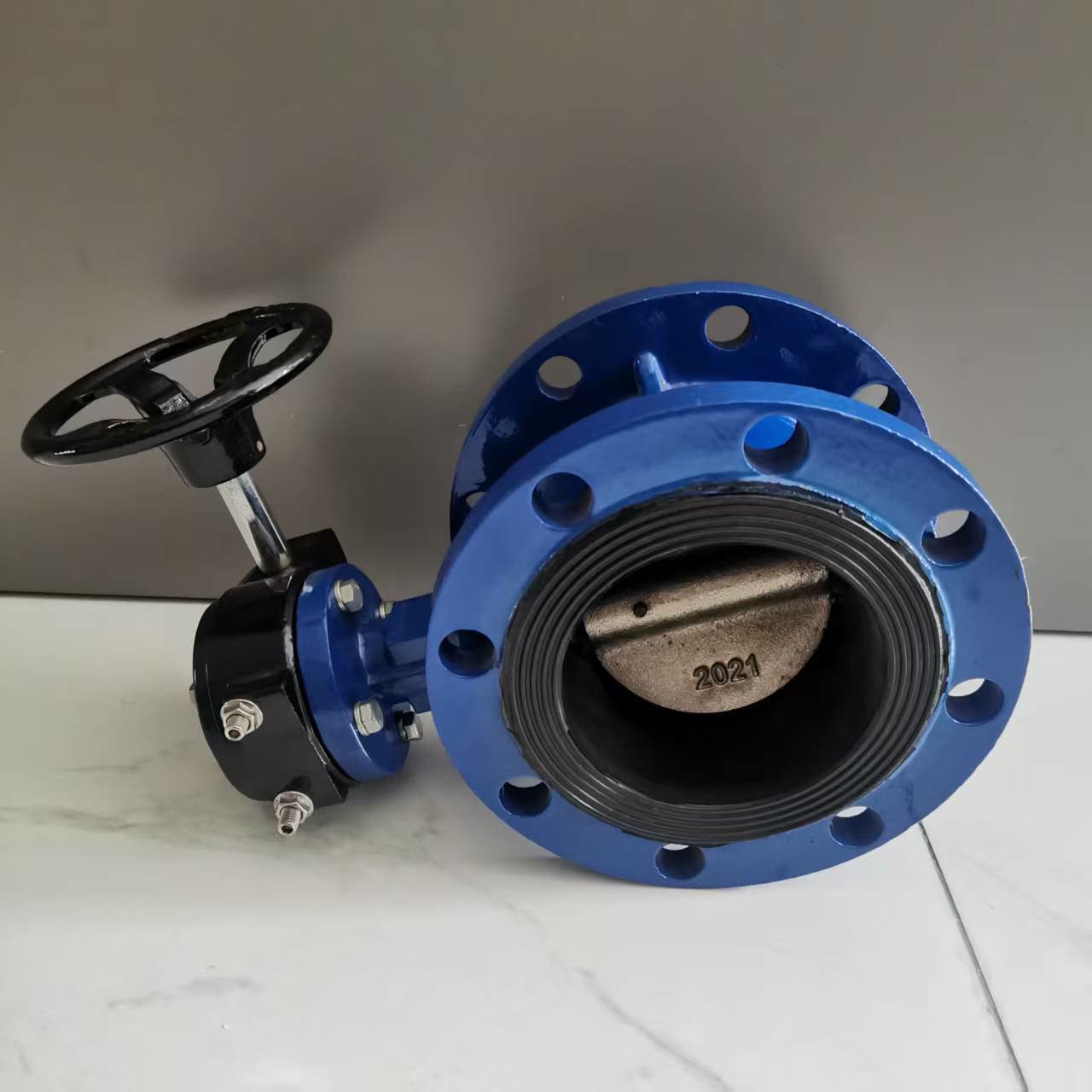
A full-flanged butterfly valve has a bolted connection at both ends. Each end is an integral flange, drilled and faced to a flange standard such as EN 1092-1 (PN ratings) or ASME B16.5 (Class ratings), and each joint gets its own gasket and bolt set. The valve is a self-contained, rigid pressure component: you can unbolt it and lift it out of the line without the pipework holding anything together.
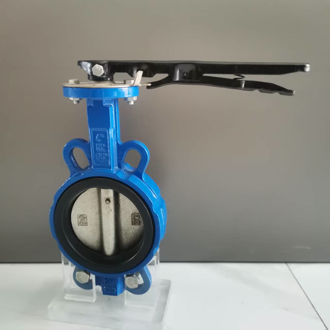
A wafer butterfly valve has no flanges. The body is a short disc-shaped cartridge sandwiched between the two pipe flanges, and a single set of through-bolts passes across the valve body and clamps both joints at once. The pipe flanges, gaskets and line bolts do all the structural work; the valve body carries only the disc, seat and stem. The result is a much shorter and lighter component.
Between the two sits the lug body, worth knowing about because quotations sometimes include it without explanation. A lug body has threaded metal bosses around its perimeter, so each pipe side is bolted to its flange independently. It installs like a wafer valve, but because the sides are bolted separately, one side of the line can be disconnected while the valve holds the other side shut. That is what makes lug bodies eligible for end-of-line duty, where plain wafer bodies are not.
Face-to-face standards and the DN100 numbers
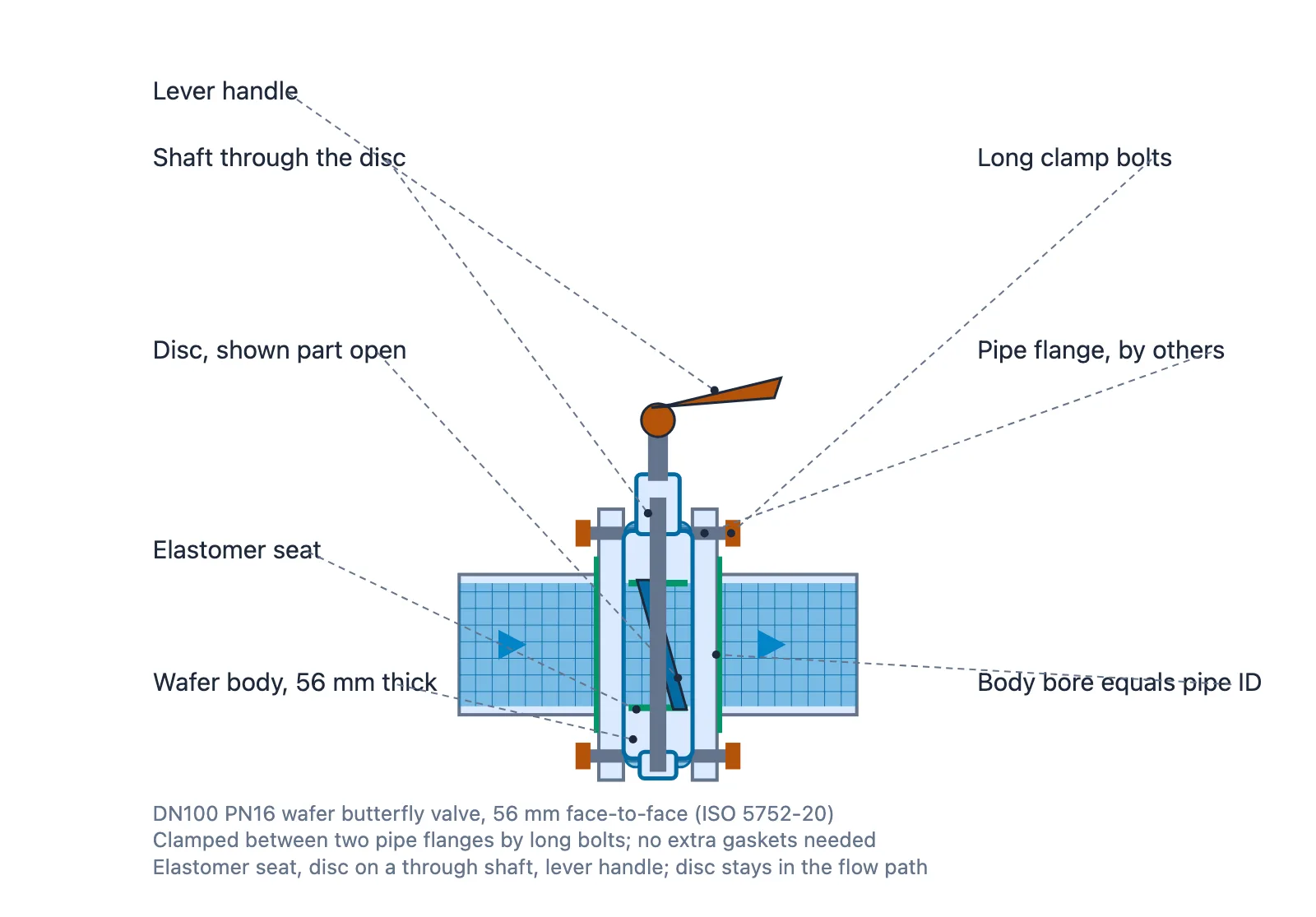
Connection type and face-to-face length are locked together by standard, which is why preference alone cannot settle the choice. In Europe and most of Asia and the Middle East, EN 558 (which absorbed the older DIN 3202 patterns) defines the face-to-face dimensions of industrial valves through numbered basic series; ISO 5752 harmonises the same dimensions internationally, and API 609 covers butterfly valves in the US system, split into Category A (wafer and lug) and Category B (double-flanged). The flanges themselves follow EN 1092-1 with PN10/PN16 ratings, or ASME B16.1/B16.5 with Class 150/300 ratings.
The two standard DN100 figures recur in almost every butterfly valve quotation:
One cross-border trap deserves its own note: a PN16 flange (EN 1092-1) and an ASME Class 150 flange overlap in pressure rating but share neither bolt count nor bolt size nor facing. A valve described as suitable for both PN16 and Class 150 will still not fit both flange patterns, because the bolt holes differ. On projects mixing European and American piping, fix the flange standard first and order valves drilled to match, never the reverse.
| Criterion | Wafer butterfly valve | Double-flanged butterfly valve |
|---|---|---|
| How it mounts | Clamped between two pipe flanges by through-bolts across the body | Integral flanges, each side bolted with its own gasket and bolts |
| Face-to-face at DN100 (NPS 4) | 52 mm — EN 558 / ISO 5752 basic series 20 (= DIN 3202 K1, API 609 short pattern) | 190 mm — EN 558 / ISO 5752 basic series 14 (= DIN 3202 F4) |
| Gaskets and bolting | 2 gaskets, one through-bolt set shared by both joints | 2 gaskets, two independent bolt sets |
| Body weight | Lowest — typically a fraction of the flanged equivalent at the same DN and class | Highest |
| Removal for service | Pipe must be spread or a spool piece removed | Unbolt both joints and lift out |
| End-of-line service | Not permitted | Permitted |
| Governing standards | EN 558 series 20, ISO 5752, API 609 Category A | EN 558 series 14, API 609 Category B, EN 1092-1 / ASME flanges |
| Relative valve cost | Lowest | Highest |
Weight, cost and space
The immediate appeal of the wafer connection is arithmetic. The body is a fraction of the length, so it uses a fraction of the material: at the same DN and pressure class, a wafer butterfly valve is routinely a third to a quarter of the weight of the equivalent double-flanged unit. Less casting, less machining, less coating, and a correspondingly lower ex-works price. Freight follows the same curve, which matters on export projects where valves ship in containers: shorter bodies pack more units per crate.
Space is the quieter saving but the more permanent one. In treatment plants, pumping stations and skid-mounted process units, pipe runs are dense. A 52 mm body against a 190 mm body saves 138 mm per valve at DN100. That is trivial on one valve and decisive on a manifold with a dozen.
The flanged valve pays for its weight in robustness. An integral-flange body tolerates rough transport handling and keeps its own geometry when adjacent pipework is loaded or disturbed. A wafer body depends entirely on the installer: the flanges either side must be parallel, correctly spaced and correctly bolted, or the short body transmits the misalignment straight into the seat and stem.
Installing a wafer butterfly valve correctly
A wafer valve is installed correctly or not at all. There is little middle ground. The procedure professional crews follow is short but strict:
1. Back the disc out towards the closed position so its edge clears the pipe bores.
2. Space the flanges with the valve in place and align them with temporary guide pins or bars. Never pull the flanges into alignment using the valve itself.
3. Seat the gaskets concentrically so the compressed edge sits dead-centre on the valve seat face.
4. Tighten the through-bolts progressively in a star pattern, alternating between both sides of the valve so the body is clamped evenly rather than squeezed from one end.
5. Re-torque the joint after the line is first pressurised, because gaskets relax.
Most wafer valve problems reported in the first months of service are installation injuries rather than faults in the valve itself: a disc jammed because the flanges were forced together over it, a liner split by over-torque on one side, a weeping joint from an off-centre gasket. Guide pins, a torque wrench and the half-hour they cost prevent every one of these.
Removal for maintenance: the part nobody specs
The wafer connection is designed around one assumption that project documents routinely forget: to remove a wafer valve, the pipe must open somewhere. The through-bolts clamp valve and flanges together, so the valve cannot simply be dropped out of a rigid line. You can spread the line with force, which is acceptable on short flexible runs but not on restrained pipework, or you can design a spool piece next to the valve at the outset. A spool piece costs little when it is drawn on the isometric in year one; retrofitting one means cutting welded pipe in a live plant.
This is the trade that flanged connections buy back. Unbolt both joints, lift the valve out, bolt the replacement in: an hour of work with standard tools. Where valves are maintenance items and seats or liners are consumables, the flanged valve recovers its purchase premium within the first removal or two. The practical rule used by experienced plant engineers: wafer connections belong where the valve is unlikely to be disturbed for its whole life, or where a spool piece exists; flanged connections belong where the valve will come back out.
End-of-line duty and higher torque
Two duties are effectively reserved for flanged or lug bodies. End-of-line service, where a valve terminates a line or closes against a line that may be opened downstream, must not be entrusted to a plain wafer valve, because removing downstream pipework would unload one side of the clamped joint. And as line size or operating torque grows, a gear operator becomes the sensible choice; a worm gear holds position securely and keeps operating effort manageable in a way a short lever cannot.
Two butterfly valves we supply
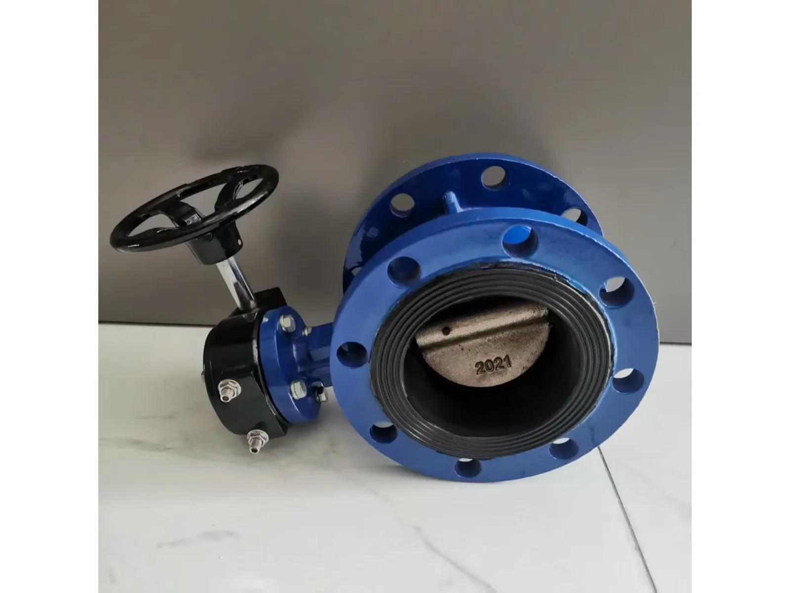
We are a trading and export company, and as a supplier we offer both connection patterns in butterfly valves. The data below is as currently listed in our catalogue; confirm the exact range and pressure class against the factory datasheet at order stage.
Wafer pattern, lever handle with lock plate. Our wafer butterfly valve D71X is listed in DN100 (4") for PN10/PN16. The body is ductile iron QT450 with an epoxy coating, the disc is SS304, and the seat is resilient EPDM. It is operated by a lever handle with a lock plate, suited to frequent on/off service in water supply lines, HVAC systems and industrial pipelines.
Flanged pattern, worm gear operated. Our flanged butterfly valve D341X is also listed in DN100 (4") for PN10/PN16. The body is ductile iron with an epoxy coating, the disc is SS304 (CF8), and the seat is resilient EPDM. Operation is by worm gear, which suits duties where holding torque matters: water mains and networks, treatment plants and industrial pipelines.
The two listings make the connection trade concrete at one size: the same DN100 line can take the 52 mm wafer cartridge or the 190 mm flanged body, and the right answer depends on whether the valve is a permanent, space-saving fit or a component that will be unbolted again.
Sources
- EN 558 / ISO 5752 face-to-face basic series 20 (wafer, 52 mm at DN100) and series 14 (double-flanged, 190 mm at DN100), with DIN 3202 K1/F4 and API 609 cross-references, as published in standard valve dimension tables.
- API 609 Category A (wafer and lug) and Category B (double-flanged) butterfly valves.
- EN 593 industrial butterfly valve requirements; EN 1092-1 PN flanges; ASME B16.5 flanges.